Power Factor Capacitor Bank Connection:
This diagram shows how to connect Power Factor Capacitor Bank Connection. Capacitor is a type of reactive element. It can store energy and provide feedback. This capacitor bank is used to reduce the distribution voltage loss. So you can wire your house or office like this diagram very easily. If you want to learn how to connect this circuit clearly you can follow our youtube video link below.
Diagram of Power Factor Capacitor Bank Connection:
 |
| Fig 1: Power Factor Capacitor Bank Connection |
Components Need for this Project:
You can get the components from any of the sites below:
- TP MCB [See Buy Click Amazon]
- Current Limit Reactor [See Buy Click Amazon]
- Power Factor Capacitor [See Buy Click Amazon]
*Please note: These are affiliate links. I may make a commission if you buy the components through these links. I would appreciate your support in this way!
Read Also:
Components used to make the Power Factor Capacitor Bank Connection:
01. TP MCB
 |
| Fig 2: TP MCB |
Three wires can be controlled by a triple pole MCB. Triple pole MCB circuit breakers are generally used in three-phase lines. A triple-pole MCB circuit breaker has three wires at its input and three wires at its output. But one can use this circuit breaker in a single-phase line. TP MCB widely used in industries. The reason is that it has three poles. And this TP circuit breaker is used to provide three-phase and three-phase connections. A neutral is not normally used in three-phase lines. But a 4-pole MCB circuit breaker is used if needed.
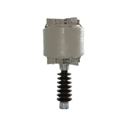
02. Current Limit Reactor
 |
| Fig 3: Current Limit Reactor |
A Current-limiting Reactor is Used When The Prospective Short-Circuit Current in a Distribution or Transmission System is Calculated to Exceed The Interrupting Rating of The Associated Switchgear. To Limit The Flow of Large Currents Under These Circumstances, Current-Limiting Reactors Are Used. These Reactors Are Large Coils Constructed For High Self-Inductance. They are also so Located That The Effect of The Fault Does Not Affect Other Parts of The System and is Thus Localized.
03. Power Factor Capacitor
 |
| Fig 4: Power Factor Capacitor |
The purpose of the starting capacitor is to provide sufficient torque to start the motor and disconnect from the circuit after the motor reaches a predetermined speed. When voltage is applied to the motor without the start capacitor, the motor will make a humming sound. A start capacitor's capacitance range is between 70 and 120 microfarads. The Start Capacitor Increases The Motor Starting Torque and Allows The Motor to Cycle and run Faster. The Start Capacitor is Designed in Such a Way That it is Used for a Short Time. They cannot stay strong for long.
Thank You for visiting the website. Keep visiting for more Updates

Post a Comment
Do leave your comments