Manual Changeover Connection | Changeover connection
Manual Changeover Connection:
This diagram shows how to connect Manual Changeover Connection. In this circuit, we use a changeover switch, a voltage stabilizer, an RCCB (Residual Current Circuit Breaker), and a single-phase energy meter. This circuit connection is very easy to connect. If you want to see connection animation please check our youtube video below the post.
Diagram of Manual Changeover Connection wiring:
Components Need for this Project:
You can get the components from any of the sites below:
- Changeover Switch [See Buy Click Amazon]
- RCCB [See Buy Click Amazon]
- Single Phase Energy Meter [See Buy Click Amazon]
- Voltage Stabilizer [See Buy Click Amazon]
*Please note: These are affiliate links. I may make a commission if you buy the components through these links. I would appreciate your support in this way!
$ads={1}Read Also:
Components used to make the Manual Changeover Connection:
01. Changeover Switch
 |
| Fig 2: Changeover Switch |
Change-Over Switch A single switching system used to operate one of the electrical systems in the absence of power from two sources (generator and PDB) is called a change over switch. Another is the PDB or Palli Vidyut Samity line made from generators or inverters. When the PDB/Rural power line is on, your company's generator line is off. Again when the PDB line goes off your company's generator line will come on again. The switching system to control these two types of electrical systems is called an automatic change-over switching system.
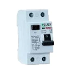
02. RCCB
 |
| Fig 3: RCCB |
The RCCB (Residual Current Circuit Breaker) or RCCB is an electrical protective device.Residual Current Circuit Breaker is specially designed to protect the electrical circuit against earth fault and human from electrical shock.In this, under normal condition the load is always connected in between the phase terminal to neutral terminal, hence the flow of phase current is equal to neutral current.Earth fault or fault in a power system can cause excess heating, more power consumption, burning or fire, etc. So, protection against earth leakage is very important.
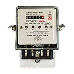
03. Single Phase Energy Meter
 |
| Fig 4: Single Phase Energy Meter |
The measuring device with the help of which the electric power or energy of a circuit is measured is called Energy Meter (Energy Meter). Also called a watt-hour or kilowatt-hour meter. For home appliances, we used a single-phase energy meter. The single-phase energy meter is directly connected between the line and the load. Both coils produce their magnetic fields, when the meter is connected to the supply line, and the load. Energy meters are used in homes and in industrial applications where we want to found that how much energy is being consumed by home appliances and electrical equipment.
04. Voltage Stabilizer
 |
| Fig 5: Voltage Stabilizer |
Voltage stabilizer is an electrical device that converts DC current into alternating current (AC). AC can be operated at any voltage and frequency system with suitable transformers, switches, and control circuits. Most electrical appliances run on AC (Alternative Current). Nowadays inverter is a very common device that is used to change the voltage in any type of machine or to control the speed of the induction motor. For example, the power supply in our country is 50 Hz, and the speed of the motor will also be fixed at this fixed Hz. In such cases inverter is used to drive the motor slowly or strongly.
Thank You for visiting the website. Keep visiting for more Updates
$ads={2}
Frequently Asked Questions
What is the mechanism of the changeover switch?
Monitoring: The automatic changeover switch continuously monitors the power supply sources, checking for the restoration of the primary source. Once the primary source is stable and within acceptable parameters, the switch automatically reconnects the load to the primary source or isolates the secondary source.
What is the change over in electrical?
A “change-over” closes one circuit and simultaneously opens a second circuit diagram. Thus a “change-over” simultaneously fulfills the function of a “normally open” or also a “normally closed” contact. This means that, in operation, a “change-over” can only ever have one connected circuit diagram closed and one energized.
What is the changeover procedure?
Simply put, a changeover is the process of converting production lines or machines from producing 1 product to another. In manufacturing, the changeover is also a measurement of the time taken to convert machines or production lines to the next product.
Why is a changeover needed?
In electrical systems, a changeover of the switch is used to switch the power supply from a primary source to a secondary source in the event of a power failure or maintenance. This ensures continuity of power supply and could be crucial for critical systems such as hospitals, data centers, or industrial facilities.
What is the changeover in the relay?
The most common changeover function relays are produced to switch a single feed line (usually Positive position 30) between two active functions in a circuit diagram. The relay is switched manually via a toggle/push switch or remotely through the circuit diagram.


Post a Comment
Do leave your comments