Float Switch Connection diagram:
This diagram shows how to connect a Float Switch Connection diagram. In this circuit diagram, we use 2 magnetic contactors, 2 single phase motors, a DP MCB ( Double Pole Miniature Circuit Breaker ), and a float switch. First, we input power to DP MCB and then from DP MCB to magnetic contactors. After this connection we make a connection with the float switch and single-phase motors. If you want to see this diagram connection animation please check our youtube video below the post.
Diagram of Float Switch Connection wiring:
Components Need for this Project:
You can get the components from any of the sites below:
- Single Phase Motor [See Buy Click Amazon]
- Magnetic Contactor [See Buy Click Amazon]
- Float Switch [See Buy Click Amazon]
- DP MCB [See Buy Click Amazon]
Read Also:
Components used to make the Float Switch Connection:
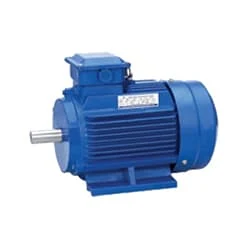
01. Single Phase Motor
 |
| Fig 2: Single Phase Motor |
02. Magnetic Contactor
 |
| Fig 3: Magnetic Contactor |
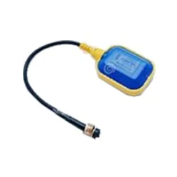
03. Float Switch
 |
| Fig 4: Float Switch |
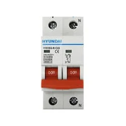
04. DP MCB
 |
| Fig 5: DP MCB |
Thank You for visiting the website. Keep visiting for more Updates.
Frequently Asked Questions
Float switches are used to detect the level of a liquid in the tank. The switch floats on top of the surface or acts as a mechanical switch, going up and down depending on the liquid level. They are often used to control pump motor devices, valves, and alarms in various residential or industrial applications.
A sump pump float of the switch detects a rise in water in a sump pump. Commonly installed in the normally closed position, the electrical circuit diagram will close as the water rises. This allows the current flow to pass to signal a pump to pump water out of the tank.
A float switch is a type of level of the sensor, a device used to detect the level of liquid within a tank. The switch may be used to control a pump, as an indicator, as an alarm, and to control other devices. One type of float switch uses a mercury switch inside a hinged float.
Also known as the liquid level of the sensors, these products contain a hermetically sealed reed switch within a stem. An external float, with a magnet inside, passes over or activates the reed switch as the liquid level moves up and down. This is shown in the below diagram. No power supply is required to operate the switches.
Overuse/Old Age – Sometimes, after so many up and down cycles, the float switch just gives out and stops responding to the rise and fall of the water in the pit. Often it stops working when the pump is running. When this happens, the pump is left off the switched on so that it runs continuously until it burns itself out.


Post a Comment
Do leave your comments