DOL Starter Motor Wiring Connection:
This diagram shows how to connect DOL Starter Motor Wiring Connection. In this circuit diagram, we just try to describe simply how to connect a DOL Starter Motor Wiring Connection Industrial loads like. This diagram is for DOL Starter Motor Wiring Connection. So you can wire your DOL Starter Motor Wiring Connection like this diagram very easily. If you want to learn how to connect this circuit clearly you can follow our youtube video link in below.
Diagram of DOL Starter Motor Wiring Connection:
Components Need for this Project:
You can get the components from any of the sites below:
- TP MCB [See Buy Click Amazon]
- Magnetic Contactor [See Buy Click Amazon]
- Selector Switch [See Buy Click Amazon]
- Overload Relay [See Buy Click Amazon]
- Drilling Machine [See Buy Click Amazon]
*Please note: These are affiliate links. I may make a commission if you buy the components through these links. I would appreciate your support in this way!
Read Also:
Components used to make the DOL Starter Wiring Connection:
01. TP MCB
 |
| Fig 2: TP MCB |
Three wires can be controlled by a triple pole MCB. Triple pole MCB circuit breakers are generally used in three-phase lines. A triple-pole MCB circuit breaker has three wires at its input and three wires at its output. But one can use this circuit breaker in a single-phase line. TP MCB widely used in industries. The reason is that it has three poles. And this TP circuit breaker is used to provide three-phase and three-phase connections. A neutral is not normally used in three-phase lines. But a 4-pole MCB circuit breaker is used if needed.
02. Magnetic Contactor
 |
| Fig 3: Magnetic Contactor |
A magnetic contactor is an electrical device used for load control, automation, and protection. It is much like a magnetic reel. However, relays are generally used for low power and voltage, on the other hand, when we think of high power, these heavy-duty contractors only come to mind. It basically works by switching the load on and off. It has 3 terminals whose inputs are denoted as L1, L2, L3, and outputs as T1, T2, and T3. The circuit of the load is made in automation mode or protection using auxiliary contacts. It has two types of terminals. 1) Normally Open (NO). 2) Normally Closed (NC)
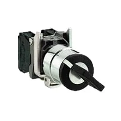
03. Selector Switch
 |
| Fig 4: Selector Switch |
Selector Switches Can be Rotated left, Right, or in The Center in Order to Open or Close The Electrical Contacts. The Function of a Selector Switch is To Control Devices as well as Switch Between a Minimum of Two or More Circuits. The perfect Use For a Selector Switch is When Used for Controlling an Output of a Device. Selector Switches Come as a Complete Unit Often listed as a Terminal Block Meaning the Selector Switch is a Complete Block Which Makes it Simple And easy to Install.
04. Overload Relay
 |
| Fig 5: Overload Relay |
Overload relays are often used to protect the motor from excessive current flow. Overload relays are used to protect the motor from overheating. Besides some specific faults such as phase to phase, phase to ground, etc. overload relay provides protection to the motor. A thermal overload relay works on the principle of bimetallic strip electro-thermal characteristics. When the bimetallic heats up, the trip function in the overload relay turns on and disconnects the power supply to the contactor coil, thus tripping the overload relay and breaking the motor current and saving the motor.
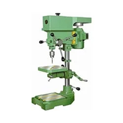
05. Drilling Machine
 |
| Fig 6: Drilling Machine |
A pillar drill machine has a motor that is used to rotate the drill bit. Different sizes of holes can be made by different types of bits. An electric drill is usually shaped like a pistol, with a switch on the handle to supply the motor power. In other words, pressing the punch switch starts the face turning; His release drills it off. In addition, almost all models have buttons on the side, next to the switch, for blocking. That way the drill continues to work despite us leaving the switch. It seems not so often when drilling, but mostly when the electric drill roars like the engine of various machines, milling machines, and turning lathes.
Thank You for visiting the website. Keep visiting for more Updates


Post a Comment
Do leave your comments