DC motor forward and reverse controller using relay:
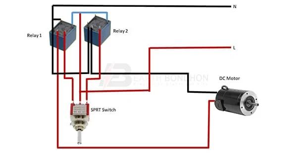
This Diagram Shows When a DC Motor is Simply Switched on, it Draws Much More Than The Normal Running Current And Develops a lot of Torque in Trying to get to Full Speed as Quickly as Possible. The DC Motor is Connected to the Availability Through the DPDT Switch, by Ever-Changing, the Switch Position we are able to get Forward and Reverse Rotation from the DC Motor as a result of this Switch Interchanges Power and Provides Polarity Applied.
Diagram of DC motor forward and reverse controller using relay wiring:
Components Need for this Project:
You can get the components from any of the sites below:
*Please note: These are affiliate links. I may make a commission if you buy the components through these links. I would appreciate your support in this way!
Read Also:
Components used to make the DC motor forward and reverse controller using relay :
01. DC Motor
 |
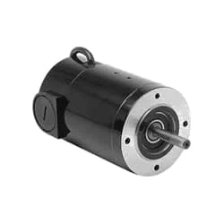
| Fig 2: DC Motor |
A DC Motor is a device that Converts Electrical energy into Mechanical Energy. A DC motor usually accepts a DC source and converts it into mechanical energy, hence it is called a DC motor. A motor in which a series field coil is connected to the armature is called a series motor. The torque of a series motor depends on the armature current, and field strength. A motor in which the field coil is connected in parallel with the armature is called a shunt motor. The torque of a shunt motor depends on the variation of mains field strength and armature current.
02. SPST Switch
 |
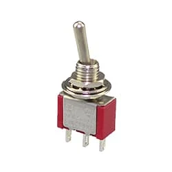
| Fig 3: SPST Switch |
A Single-Pole, Single-Throw (SPST) Switch. It's Got one Output and One Input. The Switch will Either be Closed or Completely Disconnected. SPSTs are Perfect for on-off Switching. They're also a Very Common Form of Momentary Switches. SPST Switches are Commonly Used in a Variety of Electrical Circuits and Applications, Such as Turning on And off Lights, Fans, and Other Appliances. They can Also be Used to Control the Flow of Electricity to Different Parts of a Circuit or to Switch Between Different Circuits Altogether.
03. 5 Pin Relay
 |
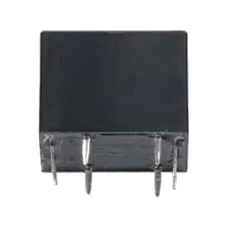
| Fig 4: 5 Pin Relay |
5 pin Relay has a coil and there are two switches between the common end NC/NO as shown in the figure. When the current is connected or sourced in the circuit, the current will always flow to the load through the normally close (Normally Close) common end of the relay. And no current will flow at the end which is Normally Open. Because when no current flows in the relay, the coil of the relay is not magnetized, and the open switch at the common end is open and the close switch is closed. Current flows through this closed switch.
Thank You for visiting the website. Keep visiting for more Updates


Post a Comment
Do leave your comments