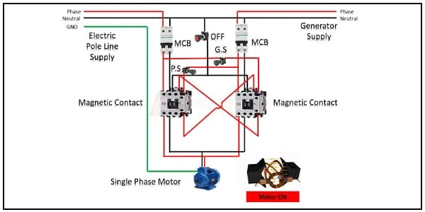
Contactor Interlock Motor connection:
This diagram shows how to make Contactor Interlocking Wiring. This article is about contact interlock. Here, you will know how to operate the contact interlock. This article also includes a contact interlock circuit and connection diagram with the motor. Contact combination systems find applications in motor starters (star-delta), power control circuits, power switch circuits, etc. When an electrical circuit has two magnetic contactors, and there only one magnetic contactor needs to be turned on, at the same time then there need the interlocking system is used for this circuit.
Diagram of Contactor Interlock Motor connection wiring:
Components Need for this Project:
You can get the components from any of the sites below:
- Single Phase Motor [See Buy Click Amazon]
- Magnetic Contactor [See Buy Click Amazon]
- DP MCB [See Buy Click Amazon]
- Push Switch [See Buy Click Amazon]
Read Also:
Components used to make the Contactor Interlock Motor connection:
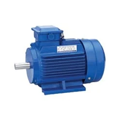
01. Single-Phase Motor
 |
| Fig2: Single Phase Motor |
02. Magnetic Contactor
 |
| Fig 3: Magnetic Contactor |
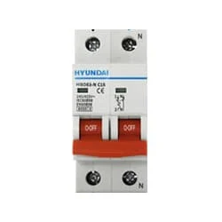
03. DP MCB
 |
| Fig 4: DP MCB |
04. Push Switch
 |
| Fig 5: Push Switch |
Thank You for visiting the website. Keep visiting for more Updates.
Frequently Asked Questions
General: Type S contactors or starters could be mechanically interlocked so that only one device is energized at a time. The mechanical interlock is an interference (non-jamming) type, locking at the beginning of the stroke of any starter and contactor.
Electrical interlock on wire mesh. An interlock device was designed to allow a generator to provide a backup power supply in such a way that it (a) prevents the main and generator power supply from being connected at the same time, and (b) allows circuit diagram breakers to operate normally without interference in the event of the overload condition.
A contactor was an electrically controlled switch used for switching an electrical power circuit diagram. A contactor is typically controlled by a circuit diagram that has a much lower power supply level than the switched circuit, such as a 24-volt coil electromagnet controlling a 230-v motor switch.
Interlocks and interlock systems could be classified into three main groups, based on the type of interconnection between the interlocks. These three groups or types were mechanical, electrical, and key interlocks. Each of these types has its advantages when properly designed or applied.
Hardwired safety interlocks are physical devices or circuit diagrams that are connected directly to the PLC inputs and outputs. They bypass the PLC logic and act independently of the software program. Examples of hardwired safety interlocks were emergency stop buttons, limit switches, pressure sensors, relays, or contactors


Post a Comment
Do leave your comments