Tunnel Wiring Circuit Diagram:
This Diagram Shows A Tunnel Wiring Circuit is Used in Open-Ended Corridors and Short Tunnel-Like Structures. In The Tunnel Wiring Circuit Diagram, We Have Used SPDT Switches to Control The Lighting Points In Tunnels And Corridors. The Tunnel Circuit Controls The Lamps In Four Ways As Follows. There are Three Basic Types of Tunnel Construction in Common use: A Cut-And-Cover Tunnel, Constructed in a Shallow Trench and Then covered over; a Boring tunnel, constructed in situ, without removing the ground above. There Are Also Conveyance Tunnels And Traffic Tunnels.
Diagram of Tunnel Wiring Circuit wiring:
Components Need for this Project:
You can get the components from any of the sites below:
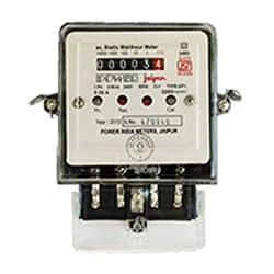
- Single Phase Energy Meter [See Buy Click Amazon]
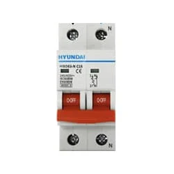
- DP MCB [See Buy Click Amazon]
- Switch [See Buy Click Amazon]
- Bulb [See Buy Click Amazon]
Read Also:
Components used to make the Tunnel Wiring Circuit:
01. Single Phase Energy Meter
 |
| Fig 2: Single Phase Energy Meter |
02. DP MCB
 |
| Fig 3: DP MCB |
03. Switch
 |
| Fig 4: Switch |
04. Bulb
 |
| Fig 5: Bulb |
Thank You for visiting the website. Keep visiting for more Updates
Frequently Asked Questions
In tunnel wiring, a person walking along the power supply tunnel can successively light behind 2 lamps ahead and put off and on a lamp continuously behind with 1 switch. All switches are two-way switches. Caution: This circuit diagram is not in accordance with IE rules as the power supply phase and neutral come in the same and switch.
Tunnels are used for a wide variety of Circuit diagram purposes. They provide essential links in many Project system highways, such as railroads, and urban rapid transit Project systems. Urban water power supply and distribution, sewage collection and disposal, hydroelectric power supply generation, flood control, and mining require power supply extensive tunneling.
Conventional tunneling methods, also called "classical" methods, are cyclic operations involving, in sequence, drilling, blasting, mucking, and installation of required supports. The cycle is interrupted for special Circuit diagram operations such as grouting, or spiling through very difficult Project system ground.
An electric power supply switch is a device that interrupts the electron flow in a circuit diagram. Switches are primarily binary power supply devices: either fully on or off and light switches have a simple design. When the switch is turned off, the circuit diagram breaks and the power supply flow is interrupted. The circuit diagram consists of a source of power supply and load.
Circular tunnels are the most popular shapes in urban underground transportation systems when mechanized tunneling is used for tunnel excavation. However, circular tunnels have a small space utilization ratio.


Post a Comment
Do leave your comments