5-Pin Relay Wiring Diagram:
This Diagram Shows A 5-Pin Relay is an Electrical Component That is Used to Control a Circuit by Opening And Closing it With The Help of an Electromagnet. It Has Five Pins, Usually Numbered 85 to 87 and 30. Pin 85 And 86 are The Coil Pins That are Used to Energize the coil and pin 30 is The Common pin to Which the Load is Connected. Pin 87 and 87a are The Switch Pins That Open and Close the Circuit When The Coil is Energized.
Diagram of 5-Pin Relay Wiring Diagram wiring:
Components Need for this Project:
You can get the components from any of the sites below:
- 5 Pin Relay [See Buy Click Amazon]
- SPST Toggle Switch [See Buy Click Amazon]
- LED bulb [See Buy Click Amazon]
- Resistor [See Buy Click Amazon]
- Battery [See Buy Click Amazon]
*Please note: These are affiliate links. I may make a commission if you buy the components through these links. I would appreciate your support in this way!
Read Also:
Components used to make the 5-Pin Relay Wiring Diagram:
01. 5-Pin Relay
 |
| Fig 2: 5-Pin Relay |
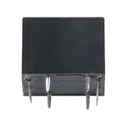
5 pin Relay has a coil and there are two switches between the common end NC/NO as shown in the figure. When the current is connected or sourced in the circuit, the current will always flow to the load through the normally close (Normally Close) common end of the relay. And no current will flow at the end which is Normally Open. Because when no current flows in the relay, the coil of the relay is not magnetized, and the open switch at the common end is open and the close switch is closed. Current flows through this closed switch.
02. SPST Toggle Switch
 |
| Fig 3: SPST Toggle Switch |
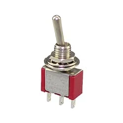
A Single-Pole, Single-Throw (SPST) Switch. It's Got one Output and One Input. The Switch will Either be Closed or Completely Disconnected. SPSTs are Perfect for on-off Switching. They're also a Very Common Form of Momentary Switches. SPST Switches are Commonly Used in a Variety of Electrical Circuits and Applications, Such as Turning on And off Lights, Fans, and Other Appliances. They can Also be Used to Control the Flow of Electricity to Different Parts of a Circuit or to Switch Between Different Circuits Altogether.
03. LED bulb
 |
| Fig 4: LED bulb |
LED (light emitting diode) is basically a type of diode that emits light at a certain voltage. These LED bulbs turn on at a very low voltage such as 2~3 volts. When the light emitting diode is forward biased, the free electrons in the n-type semiconductor gain electrical energy from the DC source and move from the balance band to the conduction band and the electrical Under the influence of pressure, current flows through the junction to P-type. In the p-type majority of carrier holes are located in the valence band. Thus basically the p-n junction becomes a light source.
04. Resistor
 |
| Fig 5: Resistor |
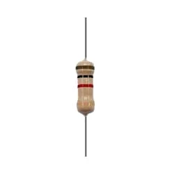
The main function of a resistor is to block the flow of current or cause a voltage drop in an electronic circuit. In short, the function of the register is to prevent the movement of electricity. When we know about electronics, the first name that comes is Resistor. It is basically a common component of electronics. This component is used in every electronic circuit. A resistor is a very familiar component to those who work with electronics. It has a special function. Resistance is denoted by R. Its unit is the ohm (Ω). The following figure shows some resistor symbols that are used in various circuit boards and circuit diagrams.
05. Battery
 |
| Fig 6: Battery |
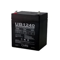
A 12-volt Battery is an Irregular Battery used in Specific Electronic Applications. Of all the types of Batteries, the 12-Volt Battery is one That Looks Very Different Depending on its use. It can be Large or small, Heavy or Light. Twelve-volt batteries are commonly used in RV, Boat, and Other Automobiles Systems. From a Technical Perspective, a Battery Uses one or more cells to Allow a Chemical Reaction Creating the flow of Electrons in a Circuit.
Thank You for visiting the website. Keep visiting for more Updates.


Post a Comment
Do leave your comments