3 Phase Distribution Board Wiring:
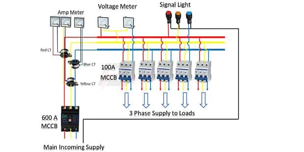
This diagram shows how to connect Three - Phase Distribution boards are panels that house the Circuit Breakers, ground leakage Protection units, and fuses that are used to distribute power to individual consumer points or Circuits Within a Building. Three-phase power Provides Three Alternating Currents, with Three Separate Electric Services. Distribution Boards 3-Phase to Manage and Distribute Electric power. Through Electrical Wiring cables and Wires The many Connected Appliances.
Diagram of 3 Phase Distribution Board Wiring:
Components Need for this Project:
You can get the components from any of the sites below:
- TP MCB [See Buy Click Amazon]
- Ampere Meter [See Buy Click Amazon]
- Voltage Meter [See Buy Click Amazon]
- Signal Light [See Buy Click Amazon]
*Please note: These are affiliate links. I may make a commission if you buy the components through these links. I would appreciate your support in this way!
Read Also:
Components used to make the Distribution Board in House:
01. TP MCB
 |
| Fig 2: TP MCB |
Three wires can be controlled by a triple pole MCB. Triple pole MCB circuit breakers are generally used in three-phase lines. A triple-pole MCB circuit breaker has three wires at its input and three wires at its output. But one can use this circuit breaker in a single-phase line. TP MCB widely used in industries. The reason is that it has three poles. And this TP circuit breaker is used to provide three-phase and three-phase connections. A neutral is not normally used in three-phase lines. But a 4-pole MCB circuit breaker is used if needed.
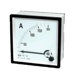
02. Ampere Meter
 |
| Fig 3: Ampere Meter |
The Ammeter (Abbreviation of Ampere Meter) is a Measuring Instrument used to find the Strength of the Current Flowing Around an Electrical Circuit when Connected in Series with the part of the Circuit Being Measured. For Direct Measurement, The Ammeter is Connected in Series With the Circuit in Which The Current is to be Measured. An Ammeter’s Current Sensitivity is Determined by the Amount of Electric Current Required by the coil of the Meter to Produce the Required FSD Movement of the Pointer.
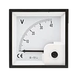
03. Voltage Meter
 |
| Fig 4: Voltage Meter |
An instrument that measures the potential difference between any two points in a circuit directly in volts is called a voltmeter. To Measure the Potential Difference Between two Points in the Circuit, the Voltmeter Should be Connected in Parallel with those two points. The working common volt meter and ammeter are similar and work on the same principle. Current flows through the coil of the voltmeter at a rate proportional to the voltage and the reading are obtained. The internal resistance of this meter is very high. The coil of a volt meter is made up of many strands of thin wire.
04. Signal Light
 |
| Fig 5: Signal Light |
An electric current Flow Indicator Senses The electrical Current Through an electrical device And produces visible feedback to Indicate Proper Operation. The Current Flow Indicator Has Voltage And Current Regulation Craving First And Second Inputs Connected To The First And Second Conductors, Respectively. This Publication Provides updated Statistics on a Comprehensive Set of social, Economic, Financial, and Environmental Measures as Well as Select Indicators for Sustainable Development Goals.
Thank You for visiting the website. Keep visiting for more Updates.


Post a Comment
Do leave your comments